What is an Ampere (A)
The ampere is a unit of current in the International System of Units (SI), symbol: A, named after the French physicist and mathematician André-Marie Ampere (1775-1836) who studied electromagnetism and laid the foundations of electrodynamics . An international convention signed at the International Electricity Exposition of 1881 recognized the ampere’s contribution to the creation of modern electrical science, establishing the ampere as the standard unit of electrical measurement of electrical current.
Ampere-Defined Transformation
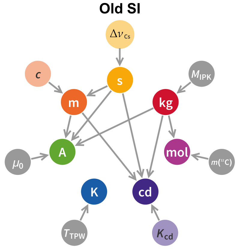
In the earlier definition of the ampere, the ampere was a constant current that, if held in two parallel straight conductors of infinite length, of negligible circular cross-section, separated by 1 m in vacuum, would produce between these conductors The force is equal to 2 × 10 -7 Newtons per meter of length. It represents the amount of electricity in one flowing coulomb per second.
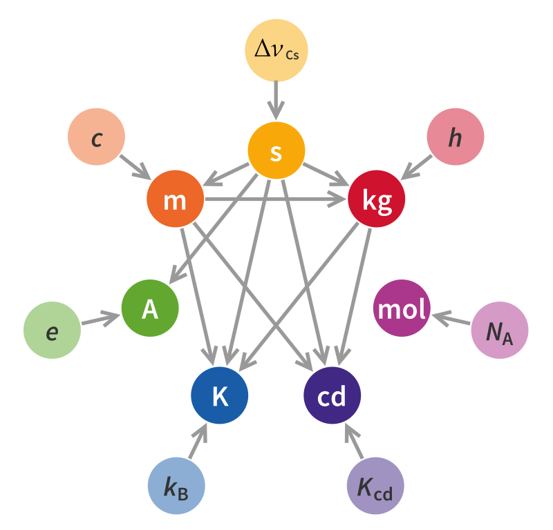
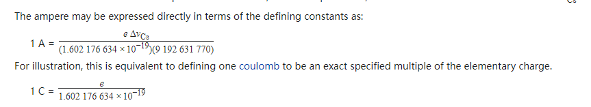
Since the SI base unit (SI) was redefined in 2019, the ampere will be redefined as a fixed value of the base charge e equal to 1.602176634 ×10 -19coulombs, i.e. the ampere is the equivalent of a current of 10 19 base charges passing through each 1.602 176 634 seconds.
What is Amp Hours (AH)
Ampere-hour, a unit of battery capacity. If a battery is discharged at 1 amp for 1 hour, it has a capacity of 1 amp hour. 1 ampere hour is equal to 3 600 coulombs. Batteries with larger amp hours hold more charge.
Amp hour is the rating used to tell consumers how much amperage a battery can provide for exactly one hour. In small batteries such as those used in personal vaporizers, or standard AA sized batteries, the amp hour rating is usually given in milli-amp hours, or (mAh). For large batteries, the rating is abbreviated as Ah. Most deep cycle batteries will tell you the Ah rating at multiple C ratings. The C rating tells you how many amp hours the battery can provide for a very specific period of time. For instance, at C/5 a battery might safely provide 26.8 amp hours. This means that is supplies 26.8 amps in the duration of 5 hours without dropping off. Meanwhile, the same battery may safely provide 36 amp hours for a period of 100 hours. Depending on the amount of use you intend to get out of your battery (daily versus sporadically), you will want to compare amp hours for different C ratings. However, if you aren’t sure which C rating to use, it is best to go with the C/20 because it is the middle ground and will give you a general sense of battery performance.

How does a multimeter measure ampere current?
Multimeters, also known as multiplex meters, multimeters, triple meters, multimeters, etc., are indispensable measuring instruments in power electronics and other departments. Generally, the main purpose is to measure voltage, current and resistance.
The multimeter is composed of a magnetoelectric ammeter (meter head), a measuring circuit and a selection switch. Through the transformation of the selection switch, it is convenient to measure DC current, DC voltage, AC current, AC voltage, resistance and audio level, etc., and some can also measure AC current, capacitance, inductance and some parameters of semiconductors (such as β) Wait.
When measuring current with a multimeter, it is necessary to distinguish between DC and AC. The following is a description of the digital multimeter:
Voltmeter principle
The greater the generated magnetic force, the greater the swing of the pointer on the voltmeter. There is a magnet and a wire coil in the voltmeter. After passing the current, the coil will generate a magnetic field. After the coil is energized, the effect of the magnet Deflection will occur down, which is the header part of the ammeter and voltmeter.
Since the voltmeter needs to be connected in parallel with the resistance to be measured, if the sensitive ammeter is directly used as a voltmeter, the current in the meter will be too large and the meter will burn out. At this time, a large resistance needs to be connected in series with the internal circuit of the voltmeter. , After this transformation, when the voltmeter is connected in parallel in the circuit, most of the voltage applied to both ends of the meter is shared by this series resistance due to the function of the resistance, so the current passing through the meter is actually very small, so the It can be used normally.
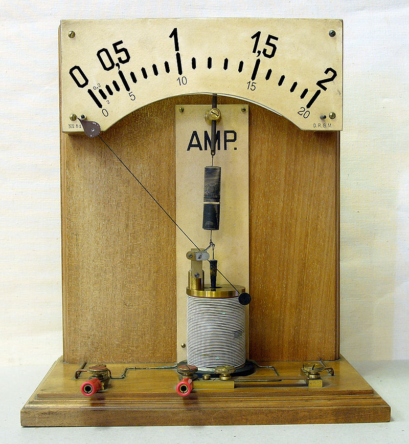
What is an ammeter, the structure and function of an ammeter
Structure and function of ammeter
An ammeter, also known as an “amp meter”, is an electrical instrument that measures the current in a circuit.
Ammeters can be divided into three categories: AC ammeters, DC ammeters and AC and DC energy meters. These three types of ammeters are used in series with the circuit to be measured in electrical equipment and circuits.
ammeter measurement basic circuit
1. The DC ammeter mainly adopts the measuring mechanism of the magnetoelectric meter.
Generally, currents in the order of microamps or milliamps can be directly measured. In order to measure larger currents, the ammeter should have a parallel resistor (also known as a shunt).
2. The AC ammeter mainly adopts the measuring mechanism of electromagnetic meter, electric meter and rectifier meter.
The minimum range of the electromagnetic measuring mechanism is about tens of milliamps. In order to increase the range, the number of turns of the coil should be proportionally reduced and the wire should be thickened.
When an electric measuring mechanism is used to form an ammeter, the moving coil and the static coil are connected in parallel, and the lowest range is about tens of milliamps.
In order to increase the range, reduce the number of turns of the static ring and thicken the wire, or change the two static rings from series to parallel, then the range of the ammeter will be doubled.
When measuring AC current with a rectifier meter, the reading of the ammeter is correct only when the AC is sinusoidal.
A shunt can also be used to expand the range. In addition, high-frequency current can also be measured with a thermoelectric meter measuring mechanism.
The large-range AC ammeters used in the power system are mostly 5A or 1A electromagnetic ammeters, and are equipped with current transformers with appropriate current transformation ratios.
3. The AC and DC ammeter can measure both DC current and AC current.
How does an ammeter work
The working principle of the ammeter is the same as that of the voltmeter. Both the voltmeter and the ammeter are composed of a meter head and a resistor.
When there is current passing through the meter, the pointer is deflected under the action of ampere force. If there is a scale on the meter at this time, the scale is the current value, which is an ammeter. If the scale is a voltage value, it is a voltmeter.
Generally, if the meter is used for measurement, the range will be very small, and the actual measurement range is not enough, so the meter needs to be modified.
An ammeter consists of a meter head connected in parallel with a resistor, and a voltmeter consists of a meter head connected in series with a resistor.
Hall Sensor (Ampere Clamp)
A clamp-type ammeter is a type of ammeter used to measure the current value in a circuit, referred to as a current clamp. In electrical and electronic engineering, a current clamp (or current probe) is a clamp-on probe with two openables that clamps the electrical conductors around an electrical device, and the probes do not need to be in contact with the conductive parts of the device, i.e., do not need to be disconnected Device leads are used for probe insertion to measure the properties of current in conductors. Current clamps are commonly used to measure sine wave current (alternating current (AC)). With more advanced testing instruments, phase and waveform can also be tested. Generally speaking, very high alternating current (above 1000A) is easy to measure, while direct current and very low alternating current (milliamp level) are difficult to measure accurately.
product description
The clamp current meter is a very common measuring instrument. The technology is getting more and more mature, and the accuracy is getting higher and higher. The basic principle of the clamp ammeter is equivalent to a current transformer, and the measured wire passing through the jaw is equivalent to the primary side of the transformer. When there is current on the primary side, the secondary side will induce a voltage to generate a current. Then, various circuits for measuring current are added to form a clamp-on ammeter. The biggest advantage of clamp current is that it is a hand-held instrument, without wiring, online detection, and convenient measurement. It is widely used in electric power, energy, transportation, elevator and other industries.
use
Usually, when measuring current with an ordinary ammeter, it is necessary to cut off the circuit before connecting the ammeter to measure, which is very troublesome, and sometimes the normal operation of the motor does not allow this. At this point, it is much more convenient to use a clamp-on ammeter to measure the current without breaking the circuit.
type
Current Transformer
This type of clamp ammeter is composed of a current transformer and an ammeter. The iron core of the current transformer can be opened when the wrench is tightened; the wire through which the measured current passes can pass through the opening of the iron core without cutting it, and the iron core is closed when the wrench is released. The circuit wire under test passing through the iron core becomes the primary coil of the current transformer, in which the current is induced in the secondary coil by passing the current. So that the ammeter connected to the secondary coil will have an indication—–measure the current of the line under test. The clamp meter can be changed to different ranges through the shift of the switch. However, it is not allowed to operate with power on when shifting gears. The accuracy of the clamp meter is generally not high, usually 2.5 to 5. For the convenience of use, there are also switches of different ranges in the meter for measuring different levels of current and measuring voltage.
Iron Vernier Current Clamp
This type of current clamp, the magnetic flux in the center of the test instrument directly drives the iron vernier of the reading, is used for the measurement of DC or AC current, and gives a true non-sinusoidal AC waveform RMS value. However, due to their physical size, they are generally limited to power transmission frequencies around 100 Hz or above.
Hall effect
The Hall effect type is more sensitive, capable of measuring both DC and AC, and is more commonly used in the kilohertz (KHz) range. This type is usually used in oscilloscopes and high-end computer-based digital multimeters, and the practical scope of these two types of current clamps is becoming more and more consistent.
Multi-core test type
Conventional clamp-on ammeters are only used to test the current of a single conductor, because if more than two are placed, the magnetic fields around the different conductors will cancel each other out. A relatively recent development is a clamp meter with several sensor coils. This type can be clamped to standard 2 or 3 single-phase conductive cables and read the current through the load. This type is an extended application, which has not been commercialized at present, but is theoretically feasible and applied in special fields.
Selection
- The clamp-type ammeter has a wide range, from a few amperes to several thousand amperes, and an appropriate range should be selected. Do not use a small range to measure a large current, otherwise the meter will burn out, and you cannot use a large range to measure a small current, otherwise a large measurement error will occur.
- Is the function of the clamp ammeter pure AC or AC and DC? Does it have other functions, such as voltage, resistance, and small current functions? Can it meet our needs.
- Whether the accuracy of the clamp ammeter can meet the needs of our current measurement accuracy.
- The rated voltage of the clamp ammeter should be higher than the voltage of the line we need to measure.
- The size of the jaws of the clamp-on ammeter. If the measurement is made of thick wires, the jaws of the clamp-on ammeter should be larger.
Precautions for use
Because the clamp ammeter is a device that measures large currents, we must consider both accuracy and safety. Usually should be checked more, if any problem is found, send it to the measurement department for recalibration in time. The following issues should be paid attention to during use:
(1) Before using the clamp-type ammeter, it is necessary to know the voltage of the line under test and whether it is lower than the rated voltage of the clamp-type ammeter, which is related to the safety of the measuring personnel and the safety of the measuring equipment. If you measure the current of a high-voltage line, you need to wear protective measures such as insulating gloves, insulating shoes, and insulating pads.
(2) In principle, the clamp-on ammeter does not measure the bare wire current. If it must be measured, stricter insulation measures must be taken. Because when the clamp ammeter is testing at the high end of the power supply, if the insulation is not good, the voltage will form a loop between the human body and the ground, causing danger.
(3) Always check whether the insulating material on the jaws is worn or not, such as falling off, cracking, etc. If there is any, it must be repaired before use.
(4) If the electromagnetic noise from the jaws is heard during measurement, or the hand holding the clamp ammeter feels a slight vibration, it means that the end faces of the jaws are not tightly combined, or there may be rust spots or dirt. , it should be cleaned immediately, otherwise it will cause inaccurate measurement.
(5) The range cannot be changed when measuring with current. The current should be disconnected and then the range should be changed. Otherwise, the clamp ammeter will be easily damaged and the measuring personnel will not be safe.
(6) The shielded wire cannot be measured with a clamp ammeter, because the magnetic field induced by the current of the shielded wire cannot pass through the shielding layer to the iron core of the clamp ammeter under test, so accurate measurement cannot be performed.
Digital Clamp Ammeter
Digital clamp-type ammeter is mainly composed of transformer-type clamp head or Hall-type clamp head (including fixed jaw, movable jaw and Hall magnetic sensor), jaw trigger, function range selection switch, measurement circuit and digital voltage basic. Table (DVM) and other components.
(1) Transformer type clamp head: Its structure, principle and function are the same as the clamp head of the pointer clamp type ammeter, please refer to the relevant content in the previous chapter. This clamp head can only detect AC current.
(2) Hall-type clamp head: The clamp-shaped magnetic core is made into a tensioned structure, and the Hall magnetic sensor (based on the Hall effect, which can detect the magnetic field and its changes) is placed on the clamp-shaped cold-rolled silicon steel sheet The clamp core is clamped outside the wire through which the current to be measured flows. When a current flows through the wire, a magnetic field will be generated in the clamp core. Its size is proportional to the ampere-turns of the current flowing through the wire. This magnetic field acts on the Hall element and induces the corresponding Hall potential, and the current flowing in it can be measured. This clamp head can detect alternating current. DC current can also be detected.
(3) Measuring circuit: including various functional converters, its task is to convert various electrical parameters to be measured into tiny DC voltage signals that can be accepted by the digital voltage basic meter.
A shunt is an instrument for measuring DC current, which is made according to the principle that a voltage is generated across a resistor when a DC current passes through a resistor.
Shunts are generally used to expand the current range with a fixed value of low resistance. Usually connected in parallel with the moving coil of an ammeter or galvanometer. There are two types of connection inside and outside the meter.
What is a shunt
Select the method of the shuntEdit
(1) Select the rated voltage drop specification of the shunt according to the mV number marked on the dial of the ammeter (or current-voltage dual-purpose meter) used (75mV or 45mV is commonly used). If the ammeter used does not have this value, use the following formula to calculate the voltage limit of the table, and then select the rated voltage drop specification of the shunt.
Voltage limit (mV) = current at full scale of the ammeter (A) × internal resistance of the ammeter (Ω) x 1000
(2) Select the rated current specification of the shunt according to the current range to be expanded.
(3) Connect the two current terminals of the selected shunt to the power supply and the load respectively, and connect the potential terminal to the ammeter. It should be noted that the polarity of the terminals of the ammeter should be connected, and the range of the ammeter will be expanded to the current calibrated on the shunt. value.
Calculation method of ammeter multiple after using shunt edit
For motor test measurement, an ammeter is often equipped with multiple shunts to solve the problem of ensuring the required measurement accuracy in a large measurement range. At this time, it is required that the rated voltage drop of all shunts used is the same as that of the equipped ammeter, such as 75mV. In this way, after the shunt is selected, the full scale of the ammeter is the rated current value of the selected shunt, and the multiple of the ammeter (that is, the number of currents per division on its dial scale) is the rated current of the shunt divided by the total number of divisions on the dial scale.
Shunts for DC current measurement are available as slotted and non-slotted. The shunts have manganese-nickel-copper alloy resistance rods and copper strips, and are plated with nickel. Its rated voltage drop is 60mV, but can also be used as 75, 100, 120, 150 and 300 mV.
Slot shunts are available in the following current ratings: 5A, 10A, 15A, 20A and 25A.
Non-slotted shunts are available in current ratings from 30 A to 15 kA at standard intervals.
Practical application
To measure a large DC current, such as tens of amperes, or even larger, hundreds of amperes, what should I do if there is no ammeter with such a large range to measure the current? This requires the use of a shunt. It is a short conductor, which can be of various metals or alloys, and is also connected to terminals; its DC resistance is strictly adjusted; when connected in series in a DC circuit, the DC current passes through the shunt, and the two ends of the shunt generate millivolt levels The DC voltage signal causes the pointer of the meter connected to both ends of the shunt to swing, and the reading is the current value in the DC circuit. The so-called shunt is to divide a small current to drive the meter indication. The smaller the ratio of this small current (mA) to the current in the large loop (1A-tens of A), the better the linearity of the ammeter reading and the more accurate. This is a common product for electrical circuits, and there are shunt measures for lightning protection.
Ammeters come in many different sizes, but the actual meter head is a standard millivolt voltmeter. For example, a voltmeter with a full scale of 75mv. Then use this voltmeter to measure the current of 20A, for example, it needs to be equipped with a shunt resistor that produces a voltage drop of 75mv when the current flows through 20A, also known as a 75mv shunt.
A shunt is a resistor that can pass a very large current. Generally, 15A or 20A and 35A ammeters require a shunt. The impedance of the shunt = the full-scale voltage of the meter mark / the full-scale current of the meter. For example, the shunt resistance of a 20A ammeter = 75mv/20A = 0.00375Ω. After the impedance is constant, according to Ohm’s law U = IR, the current is proportional to the voltage, the current is linear and the voltage is also linear, so you can use a full scale of 75mv The voltmeter shows the current current. Therefore, the ammeter used is actually a voltmeter.
How to measure large AC current? Using a current transformer, the large current is converted into a small current below 5 amperes at a certain transformation ratio, so a small range AC ammeter can be used to measure a large current, but the measured current has to be multiplied by that ratio.
What is the safe current carrying capacity of the wire?
The lines of electrical equipment are generally insulated with plastic or rubber wires. When the switch is closed, the current enters the electrical equipment through the wire, so that the electrical equipment works. Because the electrical line itself has resistance, it will generate heat when passing current, and the heat generated will be dissipated into the air through the insulation layer of the wire. If the heat emitted by the wire is exactly equal to the heat generated by the current passing through the wire, the temperature of the wire will no longer rise, and the current value at this time is the safe current carrying capacity of the wire.
How to choose the fuse correctly
Fuse, scientific name fuse, is an overload fuse used on low-voltage electrical lines. It is a protection device used to prevent short circuits and severe overloads.
In every household with a watt-hour meter installed, a fuse is generally installed on the knife switch behind the watt-hour meter to protect the electrical wiring throughout the home. Of course, fuses can also be installed on other important branch lines, such as kitchen, bedroom, living room, etc., to form multi-level protection.
When choosing a fuse, it must be noted that the rated current of the fuse is the same as the safe current carrying capacity of the fuse line. For example, through calculation, the maximum current in a household electrical circuit is 10 amps, then the fuse with a rated current of 10 amps should be selected on the knife switch of this family.
Difference Between DC Amplifier and AC Amplifier
The biggest difference is: one is DC and the other is AC
The circuit diagram has some differences
DC amplifiers can amplify DC signals or extremely slow-changing AC signals, and are widely used in automatic control instruments, medical electronic instruments, and electronic measuring instruments. Commonly used DC amplifier circuits include single-ended DC amplifiers, differential DC amplifiers, and modulated DC amplifiers.
The AC amplifier is composed of a basic operational amplifier and a feedback network. Due to the DC blocking effect of the capacitor, the drift and noise can be reduced.
For mobile applications such as RVs and boats, electrical outlets are rated for amps, 50 amps, 30 amps, 20 amps. These are the maximum amp ratings these outlets can deliver before the breaker pops out. Many people confuse these amplifiers with battery amplifiers, but they are higher voltage AC.
Why is amperage important in electrical system design?
When designing an electrical system, it is important to consider amps to understand the size of wire you must use to stay safe.
Higher amps require larger wires
As you may recall, the higher the amps, the larger the wires needed to serve the system safely. You must properly size wires and cables to not only provide high-quality power, but also prevent electrical fires.
Higher amps will increase voltage drop
A voltage drop occurs when the voltage at the end of the cable is lower than the voltage at the beginning of the cable. For example, this drop usually occurs at the end of a long length of cable.
The easiest way to reduce the voltage drop is to increase the diameter of the conductor (or wire). All cables create some resistance to circuit flow, but when designing electrical systems, it is important to take all steps to reduce resistance.
Finally, for RV and marine applications, people try to conserve battery power. So it’s important to remember that higher amps will drain more battery power.
Why is amperage important in electrical system design?
When designing an electrical system, it is important to consider amps to understand the size of wire you must use to stay safe.
Higher amps require larger wires
The higher the amps, the larger the wires needed to serve the system safely. You must properly size wires and cables to not only provide high-quality power, but also prevent electrical fires.
Products Recommended:
DEEP CYCLE BATTERIES With BMS(Marine lifepo4 Lithium Battery)


